Home

Schweiß Psychologie Vision kn in m Ozeanien Resort Handel

Convert kNm to kip-ft and the opposite | calcresource

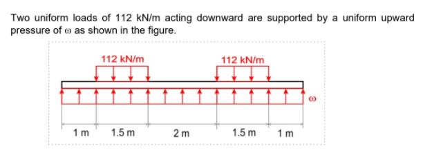
Answered: Two uniform loads of 112 kN/m acting… | bartleby

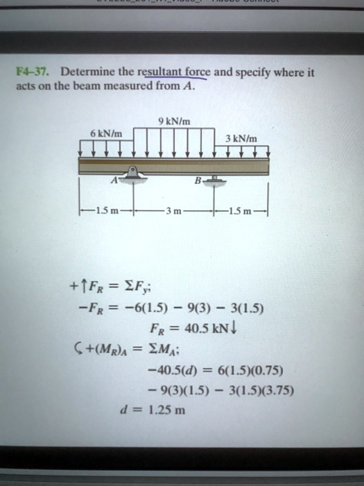
SOLVED:F4-37. Determine the resultant force and specify where it acts on  the beam measured (rom 9 KNIm KNIm KNIm 15 TFR EF ; ~FR ~6(1.5) 9(3) 301.5)  FR = 40.5 kN I C+(MR)A EMa: ~40.5(d) 6(1.5)(0.75) 9(3)(1.5) 301.5)(3.75)  1.25 m
SOLVED:F4-37. Determine the resultant force and specify where it acts on the beam measured (rom 9 KNIm KNIm KNIm 15 TFR EF ; ~FR ~6(1.5) 9(3) 301.5) FR = 40.5 kN I C+(MR)A EMa: ~40.5(d) 6(1.5)(0.75) 9(3)(1.5) 301.5)(3.75) 1.25 m

Solved Draw the shear and moment diagrams for the beam. | Chegg.com

313913386-MD2 - ghawGWFD - PART 1: MACHINE DESIGN SHORT PROBLEMS STRENGTH  OF MATERIALS A horizontal - StuDocu
313913386-MD2 - ghawGWFD - PART 1: MACHINE DESIGN SHORT PROBLEMS STRENGTH OF MATERIALS A horizontal - StuDocu

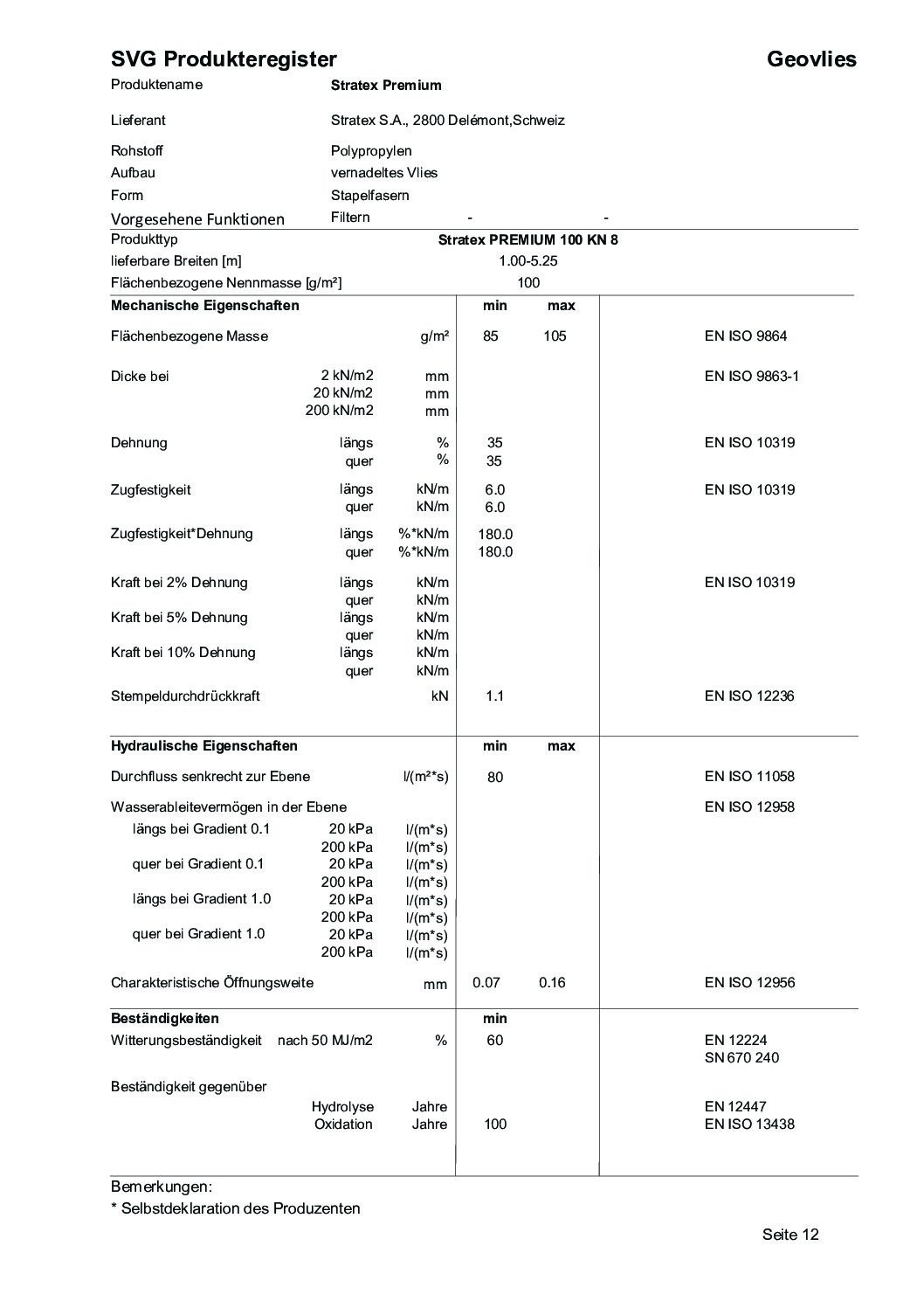
Stratex Premium KN - Stratex

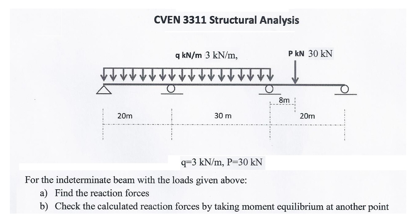
Solved q = 3 kN/m, p = 30 kN For the indeterminate beam with | Chegg.com

Solved] A cantilever beam 2.5 m long carries a uniformly distributed

A beam of length 10m is symmetrically placed on two supports 7m apart. The  loading is 15 kN/m between the supports and 20kN at each end. What is the  central deflection of
A beam of length 10m is symmetrically placed on two supports 7m apart. The loading is 15 kN/m between the supports and 20kN at each end. What is the central deflection of
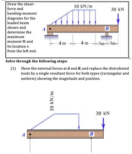
SOLVED:Draw the shear- force and bending moment diagrams for the loaded  beam shown and determine the maximum moment M and its location from the  left end. 10 kN/m 30 KN 4 m
SOLVED:Draw the shear- force and bending moment diagrams for the loaded beam shown and determine the maximum moment M and its location from the left end. 10 kN/m 30 KN 4 m

Conversions | Mah Bader - Academia.edu

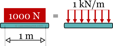
Convert kN/m to kips/ft and the opposite | calcresource

Solved] 7. A concrete slab, 300 mm thick, 5 m wide and 10 m long, is used  to s | SolutionInn
Solved] 7. A concrete slab, 300 mm thick, 5 m wide and 10 m long, is used to s | SolutionInn

14-21. The steel ingot has a mass of 1800 kg. It travels | StudySoup

Determine the length b of the triangular load and its position a on the  beam such that the equivalent resultant force is zero and the resultant  couple moment is 8 kN ⋅
Determine the length b of the triangular load and its position a on the beam such that the equivalent resultant force is zero and the resultant couple moment is 8 kN ⋅

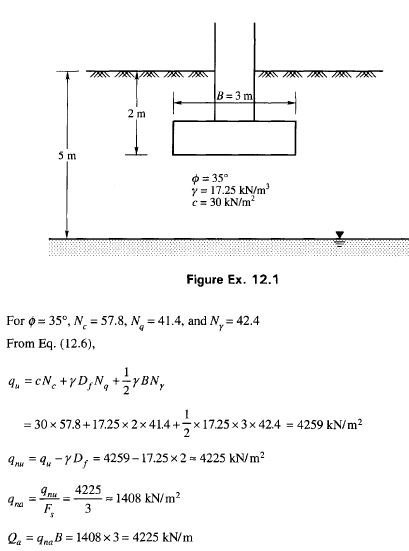
Bearing capacity problem example 1 | Civil Engineering X

Kilopascals to Kilonewtons per square meter - convert kPa to KN/mm2

Exercises of bending_518

Solved) - The continuous beam ABCD is under the action of uniform load  30... - (1 Answer) | Transtutors
Solved) - The continuous beam ABCD is under the action of uniform load 30... - (1 Answer) | Transtutors

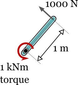
For the linear elastic beam shown in the figure, the flexural

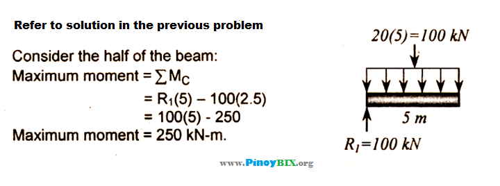
Solution: What is the value of the maximum moment of the beam due to this  load?
Solution: What is the value of the maximum moment of the beam due to this load?

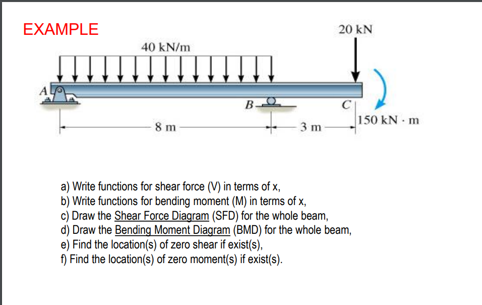
Solved EXAMPLE 20 KN 40 kN/m Α. B 150 kNm 8 m 3 m Write | Chegg.com

The beam shown in Figure P1.32 is supported by a pin at C and by a short  link AB. If w= 30 kN/m, determine the average shear stress in the pins at
The beam shown in Figure P1.32 is supported by a pin at C and by a short link AB. If w= 30 kN/m, determine the average shear stress in the pins at